- Services
- IT Support Sunshine Coast
- Web Design Sunshine Coast
- IT Blog
- About Us
- Contact Us
Tag: vlan configuration
1

This was my first real adventure into the land of vLans. I had setup very basic port-based setups before but this scenario required an 802.1Q Tagged vLan. The client runs serviced offices and required that the offices could share the internet but would not see each other on the network. The clients themselves use part of the office and had the requirement for several more ports than the other offices so it was allocated more ethernet ports on the switch. The gear used to complete the task is an inexpensive Netgear 716T 16 port Layer 2 Smart Switch and the very robust Draytek Vigor 2830n+ ADSL2+ Security Firewall Router. Normally if your client can afford it, such a scenario would be played out using High-end Cisco gear.
The outcome we looked to achieve is shown on the right.
Basically it is as follows…
- Port 1 & 2 – vlan 20 (192.168.2.x)
- Port 3 & 4 – vlan 30 (192.168.3.x)
- Port 5 & 6 – vlan 40 (192.168.4.x)
- Port 7 & 8 – vlan 50 (192.168.4.x) – same subnet as Ports 5 & 6 however the vlans keep them separated. Reason for same subnet – the Router only has the capacity for 4 subnets.
- Port 9-15 – vlan 10 (192.168.1.x)
- Port 16 – “Trunk” port to Draytek Router
Yes – if there weren’t too many devices connected to all the networks, we could have allocated all the vlans to the same subnet but we were trying to prove what could be done at the same time as creating a functional result.
First we enabled and then created the vlans in the Vlan Configuration menu in the Draytek 2830.
For some reason if every port on the Draytek is not allocated on this screen (even if it is not in use), the Draytek displays the error “Please set one vlan group at least! Please check port[x]”. If someone could tell me why this has to be done I would be interested to know. In any case we mapped vlan 10,20,30,40,50 to port 4 and allocated the subnets of LAN1-4 as shown in the image. You could set priority to the vlans if you want to prioritize certain traffic. We have not set that here. Then we enabled the various subnets under general setup and enabled DHCP on all of them. If you wanted to enable inter-lan routing you could do so here.
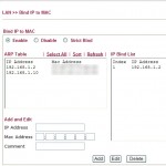
Because the GS716T has it’s own IP address for management, you will want to allocate it an IP address in the Draytek in the subnet where you want to manage it from. Find the mac address and add it to the Draytek under ‘Bind IP to MAC’. Here we gave it 192.168.1.2. The Draytek Router is 192.168.1.1.
Before plugging the two devices together, you are going to want to configure the GS716T. By default if it cannot find a DHCP server, it will use the address 192.168.0.239. Set your network card on a desktop or laptop to an address on that subnet and connect to it. You can use Netgear’s tool – the smart control center manager to find the switch or push in the button the front labelled “restore factory settings” to set it back to the default IP. The button labelled reset simply restarts the device keeping the current settings.
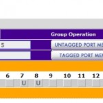
Go to the “switching” menu -> vLans and setup your various vlans. Here we have setup vlan 10,20,30,40,50 and left the defaults in the switch. Then go to vlan Membership under advanced. Select the vLan ID that you want to manage at the top. Then click on the little drop down for Port. This will open the boxes for each port. Flag each port member that you want to be a part of this vlan with a “U’ for untagged. On Port 16 that we are trunking to the router, we flag with a “T” for tagged. Press “apply” at the bottom. Do this for every port range that you want to apply to a vLan.
Now you need to setup the PVIDs – this is the default vLan ID for a port if the packet is untagged. Under Acceptable Frame Types we left this as “Admit All” becuase the other setting of “vLan only” only allows tagged vLan packets. We turned on ingress (inbound) filtering which means that only vLan traffic passes through. It works fine with this off but I figure it would stop unwanted network traffic. Make sure this is off though on your “trunk” port. We left port 16 (where we were managing from) as PVID 1 so we could continue to save the settings.
Finally set the Management vLan to the vLan you want to manage from under “System” -> “IP Configuration”. In this case vLan 10 – and apply. From this point on you will need to be on a vLan 10 port in order to manage the switch. Connect the switch and router together and your devices into the switch and watch the magic happen.You should get the correct subnets and not be able to ping other subnets (except the router).
I may have got some of the terms wrong and I’m happy for you to correct me if that is the case. I just hope this has helped someone else trying to achieve a result like this with affordable networking equipment for small businesses.
If you are on the Sunshine Coast and need Networking and IT Support, don’t hesitate to give us a call.
Quick Contact
Managed Services With FREE Credit Each Month!
 Does your IT company offer to look after your IT requirements for a Fixed Monthly Fee AND give you FREE Credits every month?
Sign up to a managed services plan with us and you get credit every month that you can use immediately or save up to use on Hardware, Software or large projects such as new server installs or office relocations.
Enquire Now or Call 5329 3200
The IT Blackhole
Do a quick survey around your office... is anyone making coffee while their computer boots? Does anyone think their computer can't keep up with the speed they like to work?
Imagine your staff lost 10 minutes a day (just 2%). Enter figures relevant to your business to see the actual cost...
OJ Networks can help. Contact us today to see how we can actually save you money.
Click for more info or Call 5329 3200 *Provided as a guide only.
Click for more info or Call 5329 3200 *Provided as a guide only.


